How to Make a Mobile Charger Using Battery
Lead-Acid Battery is the most popular. Though they are a very large size. But they have an advantage are: cheap, easy to buy. If you need a long life. You should use an Automatic battery charger circuit below.
Charging best importance
Usually, these battery types can use for 3-4 years with correctly charging. I feel sick every time the battery breaks down before the time should. I do not want you to be like me. Do not do these!

- Overheat charging
The important, battery does not like hot ! At all time, do not use or store them in too heat area.OR If while use may short circuit or high current use them will too hot. While charging does not quick charge with high current and high voltage. - DC voltage only!
We must charge them with DC voltage only. - Overvoltage charging
Normally, the battery manufacturer usually prints the appropriate voltage.
We should use a constant voltage charge.
—12V battery maximum voltage of 14.8V, Standby use is 13.8V
—6V battery maximum voltage of 7.5V, Standby use is 6.8V - High current fast charge
But hot—So you should use initial current less 30%. For example, 12V/7AH battery you should the initial current less 2A. If we use 1A, the battery will be full for about 7 hours.
- No long time
Also, If you charge it for too long times. The battery is also too hot. Thus, When the battery is full, stop charging it.
These two circuits help make your life easier.
Simple Automatic battery charger circuit
This is the first automatic battery charger circuit. We use the concept of the circuit: not using ICs and complicated devices. Use existing products to use more benefits.
We can use this circuit for all battery. Just have to understand Battery charging requirements only.
- It is designed for 12V batteries. But if you understand the working principle already. I believe you can definitely adapt for a 6V battery or others.
- You should use an input voltage of 15-volts or 1.5 times of a battery voltage.
- Most importance—Should use charger current 10 % of battery current. For example 2.5Ah battery. Use the charging current 0.25A. It will take 10-12 hour for full.
How it works
First of all, I think "When…Charge? And When stop?"
Normally we should charge the battery if the voltage is lower than 12.4V. Then the battery voltage rises and the voltage maximum 14.4V. It is full. We need to cut off the charging current.
Secondly, we need to use a comparator circuit.
I often use IC-op-amp such as LM339, LM311, LM324, LM301. But sometimes we cannot buy them.
And This our working is simple style only.
In the begin, we learn a basic principle of electronic parts.
Meet Zener Diode
I like use Diode, Zener diode, which they are both valves for electrical currents. The Current will flow one way. But the Zener diode is connected backward. It then blocks current until the voltage exceeds a certain level.
I try to test them with the Zener diode 12-volts the current will flow through it when a voltage higher than 12V.
So, I use Zener diode for detects voltage over than 13V to control stop charger system.
Relay and SCR cut-off battery
Then, I use a relay to control the current to a battery. Because of cheap and used easily.
Next, I use a SCR for uses as quick control switch.
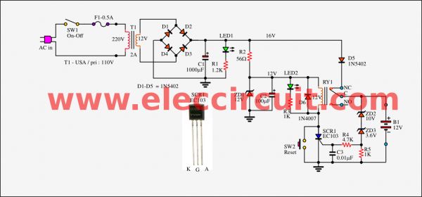
Simple automatic cut off battery charger
Comes to look in the circuit. I use it for 12V 7AH battery and lower. So the charging current is 2A.
So I use a 2A, 12V transformer in the unregulated power supply. In load or while in charge is 13V to 15VDC.
Suppose, the voltage battery is 12.4V. The relay does not work. The charging current flows continuously through the battery.
Until the voltage of the battery rises up to 13.8V. Starts to has the current flowing through Zener diode to Bias SCR1.
The SCR1 is working. Then replay also runs, pull in the NO and C connecting.
So no current flow to the battery.
How to setting and use
You can watch the video below I test it. This projects will always cut off the battery. When the voltage drops across it are 13.6V down.
Then LED2 (yellow) glow brightly. While the relay will pull out from the contact NC-C. Which no current to battery and voltage lower down.
Then you can charge again with pressing SW2 to reset, recharge them again.
High current charging
If you want to charge the high current battery. For example, 45Ah battery. You should use the current less than 5A. And less than 15A current.
Also, you need to use a high current power supply. The components inside are high current. For example 10A-15A transformer, 25A bride Diodes, 20A Relay and more.
I think this circuit is not suitable for high current battery. Because it may error charging. You need to use a constant voltage charge in PWM mode.
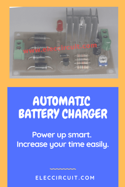
Automatic OFF 12V Battery Charger by power SCR
The circuit above may error and hard to set. I suggest an Auto dry battery charger using SCR for 12V battery. Also, it uses the 6V battery. It looks like the above circuit. The Zener diode and SCR are main parts. But the SCR works instead of the relay. The SCR is working in DC pulse on filters with a capacitor.
How this circuit works
As circuit below. To begin with, an AC220V will flow to a transformer to transform to 15 volts. Then, flow to bridge diode to rectifier AC to DC pulse 15V. The LED1 is a power indicator of the circuit.
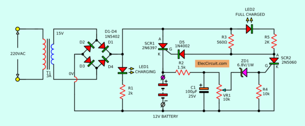
Beginning SCR1 is working. Because the 15V flow to R3, to limit the current to decrease and flow through to diode D5.
It protects the reverse voltage before bias to lead G of SCR1.
When SCR1 conducts, make the 15V flows through lead K to a positive battery terminal.
Ideally, SCR1 will conduct current and stop current alternately very fast with a frequency of 100 Hz.
Since the 15V voltage from the bridge diode is full wave rectifier. So the output frequency of 50Hz+50 Hz. The current of this feature is a continuous positive half of the sine wave.
Which it is different from the voltage with capacitor filter, that is smooth as a straight line.
So SCR1 does not conduct the current all time. When there is positive voltage to bias at lead G.
Since the waveform of voltage is DC pulse, not smooth.
The SCR will stop conducting current. If disconnecting is not a positive voltage.
Then, the positive voltage waveform comes to SCR1 again. It will start conductcurrents again, this was reversed with a frequency 100 Hz.
Battery level monitoring
To begin with, the positive battery voltage flows through R2 to reduce current. And, C1 will filter a current to smooth.
Second, the current flows through VR1 to divide voltage down. Then, the Zener diode-ZD1 pass an overvoltage to bias lead G of SCR2.
We adjust a level of VR1 to set a full battery. Until voltage at negative of ZD1 is more than 6.8V or about 7.3V.
After that, ZD1 is saturation voltage collapse flow through to feed lead G of SCR2. It causes SCR2 to conducts current. By R4 is a helper to SCR2 extraordinary stable work.
When SCR2 work, causes a negative voltage flows to lead K to A. It results to LED2 glow.
And the same time SCR1 will stop conducting current.
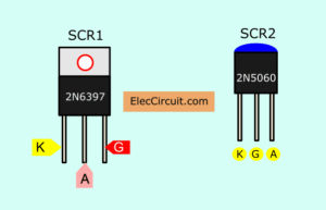
Pinout of TO-220 and TO-92 of SCRs
Since lead G of SCR1 get negative voltage from SCR2 there. In the case of battery is lower voltage, causes the voltage at negative of ZD1 is lower than 6.8V.
It makes lead G of SCR2 does not get positive voltage. But it can get only negative voltage through R4, result SCR2 does not conduct current.
The parts list
0.5W Resistors5%
R1, R5: 2K
R2: 1.5K
R3: 560Ω
R4: 10K
VR1: 10K Potentiometer
C1: 100uF 25V Electrolytic capacitor
SCR1: 2N6397__SCR
SCR2: EC103 or 2N5060SCR
ZD1: 6.8V 1W
D1-D4: 1N5404_Diode
D5: 1N4002_Diode
LED1, LED2: 5M LED as you want
PCB, and others, etc.
How to make and setting
- After you get all the components ready. Then, we soldered it successfully on PCB as Figure next checked again. For example, The device has a positive – negative. Are they correct polarity?
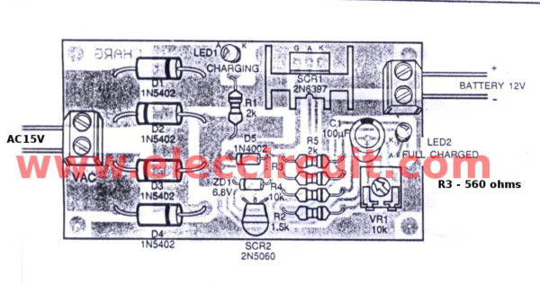
The component layout of Dry battery charger
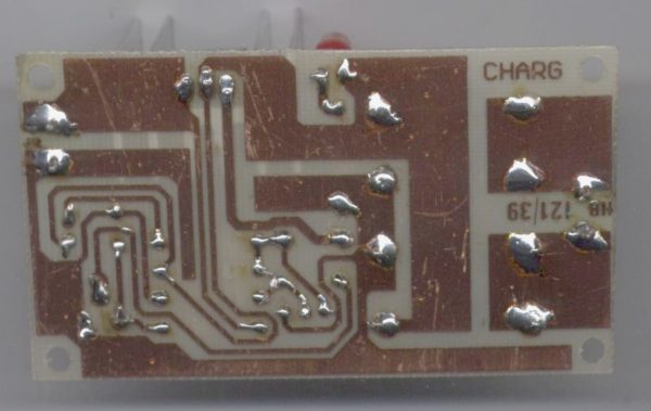
Soldering point of dry battery charger
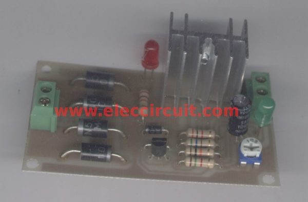
Complete assembly all parts on PCB
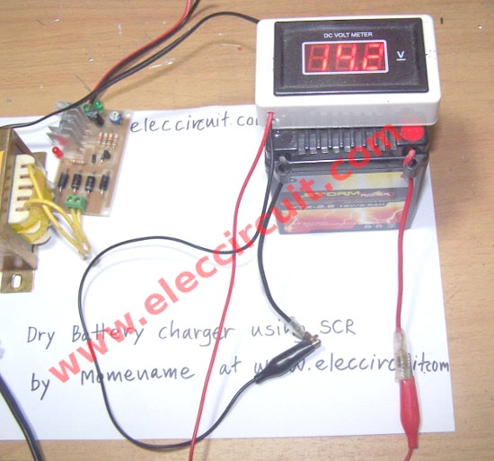
Fully 12v battery 2.5A
- To Safety, the first step, find a full battery voltage be connected to the circuit to correct polarity.
- Apply AC220V. Next, adjust VR1 clockwise until LED2 go out.
- To rotate VR1 clockwise slowly until LED2 light up, then stop immediately. Do not too much rotating.
- The principle of LED2 will light up when battery voltage until full. So, at the first time, the battery needs to be really full voltage.
Note:
I am sorry, I cannot show you the PCB layout. But you can use theperforated board.
Please watch the video below to increase understand this project.
Circuit modification
This circuit can change the battery voltage of 3 sizes 6V, 9V, 12V. We can change each value parts as a neat charged battery.
In a normal circuit, we use with 12V battery. For example, Look at the chassis battery is stated as 12V 20AH. The meaning is this can power the currents of 20 amps per hour.
When you know voltage at the battery is charged, Now I have to choose the transformer to be used. currents transformers used can be selected from 3A.
- 6V battery ; Output transformer voltage: 9V;—Zener diodes voltage: 3.3V ; —R3 and R5: 1K
- 9V battery ; Output transformer voltage: 12V;—Zener diodes voltage: 4.7V ; —R3 and R5: 1.5K
- 12V battery ; Output transformer voltage: 15V;— Zener diodes voltage: 6.8V ; —R3 and R5: 2K
Click to look more:
6V or 12V Lead Acid battery charger
Easy Many circuits easy for you
How to Make a Mobile Charger Using Battery
Source: https://www.eleccircuit.com/automatic-battery-charger-circuit/